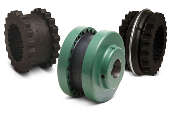
Flexible sleeves couplings are available in four materials (EPDM, Neoprene, Hytrel and Urethane) and in three basic constructions. Characteristics of the materials are given below.
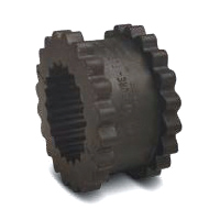
JE-JES-JN-JNS
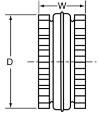
J sleeves are molded EPDM rubber (E) or Neoprene (N). They are available in one-piece solid construction (JE, JN) or one-piece split construction (JES, JNS). These sleeves may be used in any Sure-Flex Plus flange within a given size.
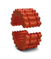
EN
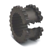
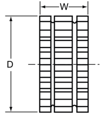
These sleeves are of two-piece design with a retaining ring. They are available in either EPDM (E) or Neoprene (N). They may be used with any flange within a given size. Sleeves are shown here assembled and disassembled.
E and N (Assembled)
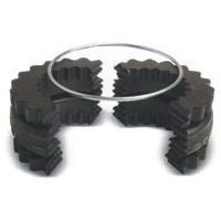
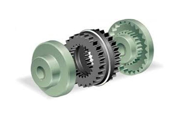
Types E and N (Disassembled)
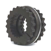
H-HS-U
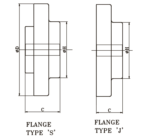
H (Hytrel) and U (Urethane) sleeves, designed for high-torque applications, transmit four times as much power as an equivalent EPDM or Neoprene sleeve. Available in one-piece solid construction (H or U) or two-piece split construction (HS), these can be used only with S, C and SC flanges. They cannot be used with J or B flanges or as direct replacements for EPDM or Neoprene sleeves.
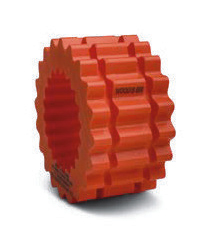
H or U
HS
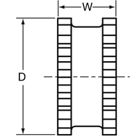
| Coupling Size | JE, JES, JN & JNS Sleeves EPDM & Neoprene | E and N Sleeves EPDM & Neoprene | H, U & HS Sleeves Hytrel & Urethane | ||||||
| D | W | Weight(lbs.) | D | W | Weight(lbs.) | D | W | Weight(lbs.) | |
| 3 | 1-7/8 | 1 | .06 | - | 1 | - | - | - | - |
| 4 | 2-5/16 | 1-1/4 | .10 | 2-5/16 | 1-1/4 | .11 | - | - | - |
| 5 | 2-15/16 | 1-9/16 | .20 | 2-15/16 | 1-9/16 | .25 | - | - | - |
| 6 | 3-3/4 | 1-7/8 | .40 | 3-3/4 | 1-7/8 | .49 | 3-3/4 | 1-7/8 | .44 |
| 7 | 4-11/32 | 2-3/16 | .62 | 4-11/32 | 2-3/16 | .77 | 4-11/32 | 2-3/16 | .69 |
| 8 | 5-1/16 | 2-1/2 | 1.13 | 5-1/16 | 2-1/2 | 1.4 | 5-1/16 | 2-1/2 | 1.4 |
| 9 | 6 | 3 | 1.46 | 6 | 3 | 2.0 | 6 | 3 | 1.8 |
| 10 | 7-1/16 | 3-7/16 | 2.32 | 7-1/16 | 3-7/16 | 3.2 | 7-1/16 | 3-7/16 | 2.9 |
| 11 | - | - | - | 8-3/16 | 4 | 5.1 | 8-3/16 | 4 | 4.5 |
| 12 | - | - | - | 9-9/16 | 4-11/16 | 8.1 | 9-9/16 | 4-11/16 | 7.3 |
| 13 | - | - | - | 11-3/16 | 5-1/2 | 13.0 | 11-3/16 | 5-1/2 | 11.8 |
| 14 | - | - | - | 13-3/32 | 6-1/2 | 21.1 | 13-3/32 | 6-1/2 | 19.3 |
| 16 | - | - | - | 17-29/32 | 8-3/4 | 45.3 | - | - | - |
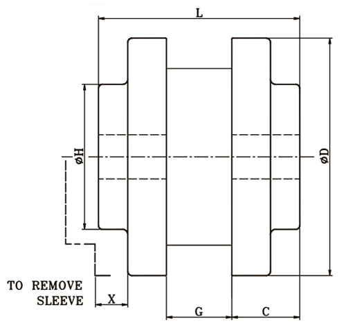
| Coupling Size | Flange Type | Sleeve Type | kW @ 100 rpm | Rated Torque | Max Speed | Bore (mm) | Dimensions (mm) | W Weight | ||||||
| N-m | rpm | P.B. | MAX. | C | D | G | H | L | X | Kg | ||||
| 3 | J | JE, JES | 0.08 | 7.64 | 9200 | 10 | 22 | 20 | 52 | 9 | 38 | 49 | 16 | 0.3 |
| 4 | J | 0.15 | 14.32 | 7600 | 13 | 25 | 22 | 63 | 16 | 41 | 60 | 16 | 0.5 | |
| 5 | J | 0.30 | 28.65 | 7600 | 13 | 29 | 26 | 83 | 18 | 48 | 70 | 23 | 1.1 | |
| S | 34 | 19 | 71 | 30 | ||||||||||
| 6 | J | 0.52 | 49.66 | 6000 | 16 | 35 | 33 | 102 | 22 | 63 | 88 | 28 | 2 | |
| S | 44 | 21 | 88 | 36 | ||||||||||
| 7 | S | 0.90 | 85.94 | 5250 | 16 | 48 | 47 | 118 | 25 | 71 | 100 | 34 | 2.8 | |
| 8 | S | 1.34 | 127.96 | 4500 | 19 | 54 | 53 | 138 | 28 | 98 | 112 | 38 | 4.8 | |
| 9 | S | 2.16 | 206.26 | 3750 | 22 | 64 | 61 | 161 | 36 | 98 | 128 | 45 | 7.2 | |
| 10 | S | 3.43 | 327.54 | 3600 | 29 | 73 | 69 | 191 | 41 | 111 | 144 | 51 | 11.2 | |
| 11 | S | E | 5.37 | 512.80 | 3600 | 32 | 87 | 87 | 219 | 48 | 133 | 180 | 61 | 18 |
| 12 | S | 8.50 | 811.69 | 2800 | 38 | 98 | 104 | 254 | 60 | 146 | 210 | 68 | 28 | |
| 13 | S | 13.43 | 1282.47 | 2400 | 51 | 100 | 111 | 299 | 68 | 171 | 235 | 78 | 48 | |
- 3 & 4 Flanges are available in Aluminium.
- 5 & 13 Flanges are available in Cast Iron.
- The Weight is approximate with solid Flanges.